
Your Cameras and Lenses are Crooked and How to Adjust Them
Plus a bunch of tidbits about some of the challenges in making astro-landscape photographs

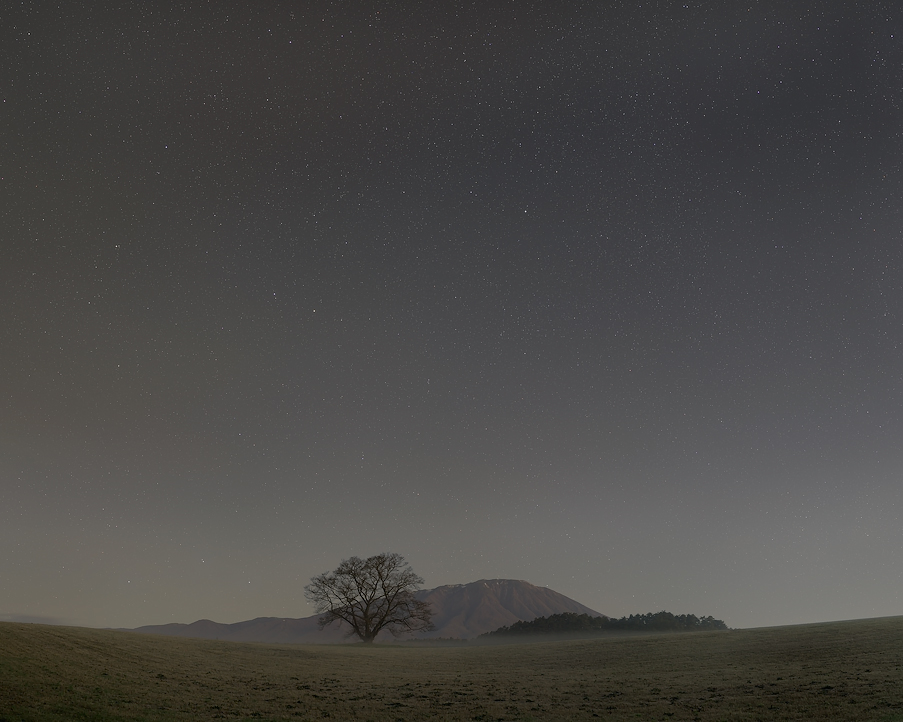
Silver River Shimmers, 2017
Photograph notes: This is a composite of 4 vertical frames stitched for the sky and another 4 vertical frames stitched for the land for a total of 93.8 million pixels, using a Sony a7R II at ISO 800 and Canon EF 35mm f/1.4L II USM. Each of the sky frames was stacked and averaged from nine 32-second exposures at f/2.8. The land frames were stacked and averaged from four 32-second exposures at f/4 made 23 mins later at predawn to avoid shadows from the sun. 52 exposures were used in all. The sky exposures were tracked with a Sky-Watcher Star Adventurer.
Contents
TLDR Preface
Introduction
Choosing lenses for astrophotography
Establishing some standards
Your camera’s sensor is crooked
Adjusting the camera
IBIS Variation
Adjusting the lenses
A better Giant Ruler
Yet more alignment pitfalls
Possibly another method
Conclusions
TLDR Preface
In December 2017, it was first suggested to me by my friend and esteemed colleague, Joseph Holmes, that my Sony α7R II’s (or more commonly written as a7R II) image sensor might be crooked relative to its bayonet mount. Don’t laugh yet, it’s not a problem exclusive to Sony. I had previously known about the same problem with digital medium format backs from precisely the same person, who put out two extensive articles on the topic over a decade ago, here and here. Neither of us wanted to believe this initially. One would certainly like to assume that 35mm format camera manufacturers, making single-unit camera bodies rather than modular system digital backs, could hold the sensors to tight enough tolerances with today’s technology. Alas, we discovered that it was not quite good enough for what we wanted from our cameras.
A diffuse and complex story unfurls, necessary for the explanation of small details in great detail. For anyone wanting the very best out of their modern, wide-aperture, breathtakingly-sharp lenses, on equally modern, high-resolution (read: highly revealing of alignment errors) digital cameras, photographing the most optically demanding subject matter in the known universe—the starry night sky—you will want to sit up and pay attention. It’s entirely fine if one does not care about subtle differences between what’s in-focus and out-of-focus. I would not soon be forgetting how many failed to appreciate the camera-shake induced blurring of the Sony a7R’s violent shutter mechanism. If one only wants photos displayed no larger than Instagram thumbnails, none of this is pertinent and you should stop reading now. Alright then, some good news! We have fortunately found reasonable solutions to the worst problems. I share them below freely.
Introduction and some background on astro-imaging
I’ve held for some time a passing interest in astrophotography. I don’t live in a country where there are dark enough skies for a great picture but the rapidly rising popularity among landscape photographers meant it often filled my social media feeds. It’s hard to ignore so compelling a thing—our view of the universe, as it were—and the humbling smallness of our existence within the grand scale of all else.
I am drawn in particular to what is called astro-landscape photography, which is typically a wide-field view of the night sky paired with some kind of interesting foreground landscape. Pictures of faraway things like planets, nebulas and galaxies are known as deep-sky astrophotography, requiring long telephotos or telescopes to magnify the tiny portion of sky they subtend, affixed to a tracker to counter the movement of the stars, which is actually the rotation of Planet Earth itself (stars also move relative to each other but not on a time-scale that matters to photography). To make many of the otherworldly pictures like what NASA publishes, folks usually have to sit around all night, sometimes for many nights, making hundreds or more exposures to gather infinitesimally small numbers of photons coming from these faraway celestial beings. They can usually afford to use smaller apertures and wait around a long time for good seeing conditions, thus avoiding most of the pitfalls I cannot.
Making astro-landscape pictures may sound the same at first but is actually quite different, and arguably a lot more challenging. Most photographs you’ll find on the web are not made using the process detailed below, rather they are single-frame wide-angle images at an extremely high ISO setting with the camera usually on a tripod with no tracking device used. The 500-rule is nowhere near stringent enough to avoid trailing and even the 200-rule is not quite enough, not to mention the latter forces one to use relatively short shutter speeds, making noise worse. Some may do some simple exposure stacking to reduce noise, but still without the use of a tracker. These look OK at Instagram sizes but upon enlargement, betray many quality issues. Often, the stars have noticeable trailing, the roundness of stars off-axis are distorted from spherical aberration, coma and astigmatism among the various higher-order aberrations and colour-fringed with violet from longitudinal chromatic aberration. The brightest stars are usually overexposed and clipped, appearing harsh. Meanwhile, the entire image is grainy due to high levels of noise, which is worse in the light-starved image corners from strong lens vignetting. Finally, the pixel resolution is never quite enough for a large print. I can sometimes notice these issues even at Instagram sizes. None of this is satisfying, to us at least.
To get the kind of pictures we are after, firstly, one has to find some interesting foreground landscape that faces the portion of the night sky of interest, at the right time of the year. Ideally, no sources of intense light pollution will be on the map for at least 100 miles in all directions, though something like 500 miles or more is best to avoid the unmistakable glow on the horizon which the camera will see, even if our eyes cannot. Access to such locations at night may be challenging, perhaps requiring camping in wilderness or hours of trail hiking in the dark. We also like to make single-row or multi-row stitches to be free of the aspect ratio of the camera but mostly to gain significantly more pixel resolution for beautiful large format prints. To eliminate streaking by UFOs (satellites, planes and other space junk zipping around the Earth) and also to increase the signal to noise ratio, we generally aim to make ~10 exposures per camera angle to be aligned, stacked and averaged later. Each of these exposures is typically 32 seconds long. To avoid trailing stars we mount our setup on a tracker (equatorial mount). We prefer to make exposures of the sky and land in the same session, so for the sake of expediency to gather enough light, we need to expose with an aperture of at least f/2.8. The camera should offer sufficiently high resolution natively so we can avoid standing around for too many additional hours, collecting more frames for stitching to achieve high levels of detail. The presence of any moving clouds, changing airglow or an aurora make it exponentially more challenging. It is a dignified rush to catch as many of these rare photons as quickly as we can.
Usually, a three-hour session is about all one can tolerate, as the stars would have shifted so much relative to the landscape it would be impossible to marry the two thereafter. The foreground landscape is photographed separately, with no tracking, obviously. I have no interest in making elaborate fakes by using skies from a completely different time and place than the landscape, yet it is impossible to achieve the level of refinement we want from a single night time exposure either, so some compositing is necessary to reveal the elusive beauty of the night. I try to recreate something close to what I experienced, within reason. It goes without saying that the editing process to make such a thing is by no means straightforward. After 15 years of study of digital imaging processes, astro-imaging is easily the hardest thing I’ve ever attempted. Add to that the complication of travel in an unfamiliar foreign country, and the hunt for worthwhile landscapes during the day, is already hard enough on the planning and preparation. All of the above sounded way too complicated in the beginning to be enticing.
In late summer of 2016, Joseph made his first serious attempt at such a picture in Yosemite. I was really turned on when I saw it. Soon after, I reasoned the possibility to seriously tackle this kind of photography and make special images of uncommon quality. We began discussing star trackers and shopping for lenses, his enthusiasm fuelling mine, him doing many lens tests early on by buying multiple copies of the same lens, returning the duds. My situation and local availability prevented me from doing the same. This is a necessary process to objectively pick the best examples of each lens we would like to have. While we wish modern precision manufacturing guarantees two of the same thing to be very much alike, the reality is that the pixels on our also-modern high-resolution cameras are something like 3-5 microns across and incredibly good at revealing minuscule differences between lenses. Every lens we have looked at is usually more than a little different from each other. I’ve not yet encountered a single design where I could not tell apart the optical behaviour of individual copies with the right kind of test subject.
Because so many lenses were evaluated simultaneously, Joseph eventually noticed that their plane of focus tended to be tilted in the same direction, meaning the plane of focus was falling nearer on one side of the frame and further away on the other. Ah ha—a trend, revealing a problem of a different nature. Maybe the camera’s sensor is crooked relative to its bayonet! It’s referred to as ‘swing’ in the horizontal direction, and ‘tilt’ in the vertical direction, but as the skew can happen at any degree of rotation not orthogonal to the sensor’s rectangle, I often refer to it as tilt unless speaking specifically about the horizontal and vertical direction. Try not to be confused. Guess what, both the lenses and cameras are crooked, but how on earth can we isolate the error contributed by each, and what can we do about it?
These are some of the issues which I will address:
1. Optical deficiencies of the lens (aberrations, variance, vignetting, field curvature, field tilt)
2. Bayonet mount machining imprecision of both the lens and camera body, causing the mating of the two to be affected
3. Parallelism of the camera’s sensor relative to its bayonet mount
Lone Cherry Tree and the Northern Stars, 2018
Photograph notes: This is a composite of 20 horizontal frames in a 4×5 multi-row stitch for the sky and 6 horizontal frames in a single-row stitch for the land for a total of 296 million pixels, using a Sony a7R II and Voigtlander 65mm f/2 Macro APO-Lanthar. The a7R II was set to continuous high-speed mode as a workaround to turn off spatial filtering which ‘eats’ stars but reduces the raw file data depth to 12 bits. Each of the sky frames was stacked and averaged from as little as eight to as many as twelve (most were nine) 32-second exposures at f/2.8 and ISO 640. The land frames are single 32-second exposures at f/11 and ISO 100 made 8.5 hours later at predawn to avoid shadows from the sun. 195 exposures were used in all. The sky exposures were tracked with a Sky-Watcher Star Adventurer.
A few words on perfection and straightness and flatness and parallelism: I’m speaking from my own perspective of the kind of pictures I’m interested in making, which may not be the kind of thing you’re after. I’m generally aiming for about 100 million pixels in the final result, though what I’ve seen from ~300 million pixels to make really large prints that are virtually flawless when inspected from 6 inches away is highly alluring, like the one above. I’m currently looking at a 40×50 inch print of it. Non-photographers with no particular interest in astronomy who have seen it, understand how satisfying the effect is. I’ve surprised even myself with it. This approach, of course, precludes many kinds of creative compositions but I’m not bothered by that for the time being. Such requirements place extreme stress on all system components to perform optimally, sometimes exceeding what they are designed for.

Lone Cherry Tree and the Northern Stars, 2018: closeup detail
Need I say it again? Never, ever assume your camera (or lens) is straight, no matter who makes it.
Choosing lenses, evaluating them and various problems unique to astro-imaging
Imaging the night sky can essentially be thought of as a wide-field Point Spread Function (PSF) test, and to rub salt in the wound, it is in continual motion due to the rotation of Planet Earth. What is that, you might ask? A PSF test evaluates how a lens distorts light in the shape of a tiny, round point. Instead of reproducing a perfectly sharp and round dot, most lenses will spread and smear that dot around due to inherent optical imperfections.
Well, if you are familiar with the MTF testing published by the folks at Lensrentals using OLAF, this is what they are doing, minus the motion. Stars are essentially perfectly round, tiny points of light, of widely varying brightness, set against a very dark background, which stresses the camera sensor’s dynamic range too. There’s no lens that can render these perfect points perfectly across its imaging circle, as OLAF at Lensrentals demonstrates. I don’t know of any lens remotely close to perfect at f/1.4. This is the most severe and revealing test of the way a lens draws light.
Also, stars are effectively all at an infinite distance to a lens on Earth. Thus the field curvature needs to be as flat as can be, something most lenses do not exhibit. Add the need for optical perfection at very wide apertures, it is like hunting for a fantasy lens. I knew going in that this was going to be challenging but never imagined it would be quite this formidable.
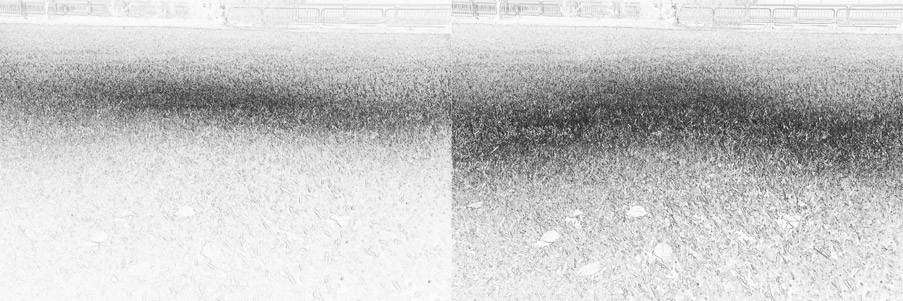
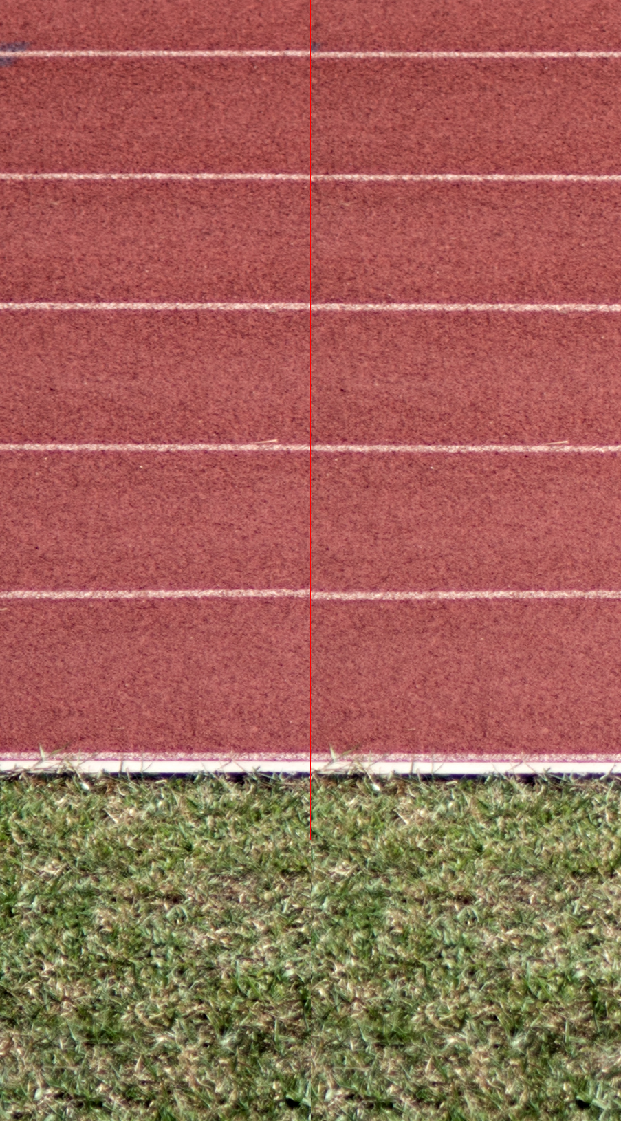
A quick and highly revealing test (it’s also Roger Cicala’s favourite, check out the link at the bottom of this article) of a lens is to photograph a flat lawn or gravel/tarmac/pavers in a carpark, focusing in the middle, ensuring there is a clear region that is out-of-focus in front of and behind the plane of focus. Then run Photoshop’s Find Edges (or GIMP’s Edge Detect Sobel filter) and desaturate the result. The filter picks out in-focus edges with dark outlines, allowing you to see field curvature with ease. From this, you can also observe any asymmetry/de-centering of the lens, detect astigmatism, resolution falloff and observe for swing and tilt (turn the camera into the vertical orientation and shoot again). This was shot with a Canon EF24-70mm f/2.8L II USM at 42mm, the left image is shot at f/2.8 and right is f/5.6. Note the band of dark matter grows lighter to the edges in the f/2.8 image. The lens is also focusing nearer on the right image edge. You might think field curvature has increased by stopping down, but in fact it hasn’t. Field curvature is actually invariant with aperture. Rather, multiple optical aberrations and poor resolution off-axis due to being wide open are obscuring the true curvature. Nonetheless, we may not be able to perceive the true curvature wide open, so remember to test a new lens at multiple apertures (and multiple focal lengths for zooms). But stop down too far and everything gets picked up by the Find Edges filter. It’s a relatively coarse edge-detect filter, so do look at the actual image too when making critical evaluations.
It’s certainly possible to image the Milky Way over the course of several months and stitch together a giant reference image (Wei-Hao Wang has made an impressive one), which one can handily drop into any random landscape. It would be easier. I can stop down to shoot – less demanding on the optics and perfect alignment. I don’t have to worry about seeing conditions. But this is pushing it too far for me, not to mention one misses the novelty of having any pretty clouds or airglow or even auroras that might occur. I would much rather be out under real stars than on the computer cooking up fake scenery.
The recent development of many fine wide-aperture lenses, probably accelerated by the extraordinary progress in high-resolution image sensors, was encouraging for what we wanted. Few of the older lens designs were worth considering. Not so long ago, a lens that gave you sharp corners at f/11 to f/16 was considered decent, and sharp by f/8 was very good indeed. You would never dare to dream of one that is great at f/5.6, let alone f/2.8. It would have been too bulky and too expensive to be practical, and they simply didn’t exist anyway. But now, several designs appear to reach their peak sharpness on-axis at f/2.8 and in the corners by f/4 to f/5.6 without breaking the bank or your back. Truly incredible.
For a time, I considered Zeiss Otus lenses (BTW they are made by Cosina in Japan, not by Zeiss in Germany) to be reference lenses. But after a lot of looking, I determined none were good enough to justify their physical heft and cost. The 55mm suffers from too much variation and together with the 28mm, are unable to render PSFs as points in the corners. Their wide-open resolving power has also been surpassed by more recent designs. The Otus’ falloff performance isn’t exemplary either, despite their massive size. Disappointing. We would generally like the vignetting at the outer 25% of the image edge to be under half a stop and preferably under 1 stop in the extreme corners, otherwise, the gradient of noise across a stitch might be too obvious.
Perhaps, you argue, having good corner performance doesn’t matter if one is stitching. Well, yes, but only to a degree. In a single row stitch, the central portion of the short edge of the sensor is used in the final result, which is more taxing on the lens as it is further off-axis than the central part of the long edge of the sensor. Also, the distortion of points don’t only occur at the extreme edges and suddenly magically disappear away from the extreme corner. It’s a gradual effect, less but still present and you can actually see the orientation of the distortions depending on their radial position, which could cause a stitching seam to become visible—oh the horrors! Fewer messes are always welcome. Furthermore, if one has to depend on a single-frame result, you would be thankful for a good lens.
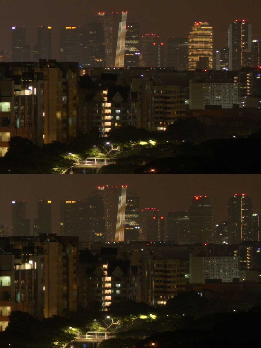
Generally, one assumes they want as wide a focal length as possible for a general-use wide-field night sky lens but I have yet to find one under 35mm that I really like. The web is awash with zillions of lens reviews and people will invariably find their own favourites. Just remember to also test your lenses at infinity or near-infinity focus, if you want to use it to shoot stars. A lens can surprise you by looking OK when shooting a chart on a wall 6 feet away but not at 1000 feet. Faraway city lights are another great test subject too. They are awfully similar to a PSF test and unlike stars, they don’t tend to move!
The Sony GM 24mm f/1.4, Sony GM 20mm f/1.8, Voigtlander Nokton 21mm F1.4 and Zeiss Loxia 25mm f/2.4 all seemed to be good contenders for a Sony system, though each has its own irritating issues. I didn’t pick any in the end. The new Nikon Z f/1.8 primes seem to be pretty good too, judging by the praise Marianne Oelund lavishes on them and her nifty coma illustrations on the DPReview forums. We have typically regarded Canon quite highly when it comes to variation control though I’ve had unusually bad luck with their lenses. Unfortunately, their sensors have not been as good as we would like in recent years. Sigma’s chief lens designer, an astro-enthusiast himself, has been the main driver for many of their new large-aperture, astro-orientated primes. They make many lenses of interest but getting good copies have proved surprisingly hard despite their claims of testing the MTF of every lens leaving the factory. Samyang/Rokinon makes some surprisingly good designs for astro work at unbelievable prices, but good luck finding a good copy. Something’s got to give at such low prices (Lensrentals has torn down their lenses and found questionable hardware). The same goes for the many Chinese lensmakers that have flooded the market in recent years.
All the mirrorless native AF lenses use fly-by-wire electronic manual focus systems. Very few feel good to me. They are usually not sensitive enough to small and slow input, the rotational ratios are not intuitive and many feel non-linear and thus unpredictable and imprecise. The Nikon Z lenses I’ve tried are dreadful, so are the early Sony E-mount lenses. Zeiss Batis lenses are somewhat better in this regard but still not super good. Recently, I played around with a few Canon RF lenses and they left a very good impression, so hope springs eternal. One could also make a case for the advantages of a true infinity focus stop, found on some manual focus lenses but never on these fly-by-wire types, given how challenging it can be to focus accurately on stars. Beware the wide range of temperatures one may have to operate in. Consequently, due to expansion or contraction, the infinity stop won’t necessarily be infinity.
After some estimates of the various angles of view of potential compositions and a lot of reading of Roger Clark’s articles, I arrived at a similar conclusion. He uses a Sigma 35mm f/1.4 Art for most of his astro-landscape ‘mosaics’, stitching as much as needed to get a wider field of view, taking advantage of a potentially sharper lens (longer lenses tend to be better off-axis) with potentially less vignetting (wider lenses tend to have more), getting higher pixel resolution in the final result to boot. I initially preferred the Canon EF 35mm f/1.4L II USM over the Sigma in my own tests. Alas, after evaluating multiple copies (if memory serves, I inspected 7) and purchasing two, I never found one that was sufficiently optically centred. Plus inherent to the lens design is a complex M-shaped field curvature not nearly flat enough by f/2.8 and worst of all, every copy had a focus field that was tilted by some non-trivial amount. It had to go.
This article will be 10x longer than it already is if I go into any more detail about what didn’t work. Let’s talk about the three successes I’ve got for the moment: I eventually replaced my Canon EF 35mm f/1.4L II USM with the Sigma 35mm f/1.2 DG DN Art, though I cannot wait for the day Cosina makes a Voigtlander 35mm f/2 APO-Lanthar (they since have, praise be!). The Sigma is outstanding but it is much too large and heavy to travel with, and I still don’t really like the fly-by-wire manual focus feel. The Sigma has low coma and astigmatism in the corners, minimal falloff, high sharpness across the image circle and relatively well-behaved field curvature which is largely overcome by using compromise focus.
I also considered the highly-regarded Tamron 35mm f/1.4 SP Di USD and tested a copy, but it did not perform as well as my Sigma despite the lavish praise Roger Cicala heaped on it. His MTF tests suggest it might be the best-resolving SLR 35mm focal length lens ever made, barely edging out the Sigma. However, when stopped down to f/2.8, I found the Sigma improved more dramatically than the Tamron (less CA, falloff, more uniform sharpness, less coma in the corners) and has better behaving field curvature. The 10-or-so-copies MTF averages that Roger publishes can make a lens look very nice, but the reality is that individual lenses don’t perform so uniformly all across their image circle. Averaging makes better copies look a little worse, but it also smooths out bad copies’ performance. Most copies will have some kind of fatal flaw upon close inspection – expect this. Often we would notice that one or more corners aren’t as good as the sharpest corner.
Then there are the now-legendary Voigtlander 50mm and 65mm F2 APO-Lanthar lenses made by Cosina in Japan, both of which I also own. Exceptional in every way (if you don’t need autofocus), both are optically superb for imaging stars. There are no average reviews for these lenses. I consider Cosina to be one of the finest lens makers in the world today. Have a look at their ‘special contents’ page where they reveal the lengths they go to make their lenses. The care they take in the smallest details is overwhelmingly evident. I cannot recommend each more highly, especially the 50mm, inspired by the Leica APO Summicron 50mm f/2, and Cosina’s optical designer benchmarked its performance against the Zeiss Otus. It is much better than either of those for my purposes. In one high-resolution sample I’ve seen of the newer (and supposedly better) Leica APO-Summicron-SL 50mm f/2, my copy of the Voigtlander seems to perform better. It’s only about a fifth of the price, by the way. And much smaller and lighter since it doesn’t have an AF system.
Oh, one more thing. Joseph discovered that the vignetting data published in virtually every lens review we looked at is wrong. What a thing to uncover after all this time. Any testing that is using Imatest’s method or not based on linear raw data is not going to give you the true vignetting performance of the lens. They either evaluate vignetting after a tone curve is applied to raw data e.g. processed images from raw converter, in-camera jpegs etc. (not linear) or assume that a contrast increasing S-curve has already been applied and so apply another arbitrary curve to inverse it (Imatest method). If the inverse curve is not the perfect inverse of the applied contrast curve (it almost never is), you don’t get the true vignetting of the lens. Many of the published vignetting graphs for Zeiss mirrorless format lenses are after software compensation, be aware when looking at them.
Thankfully, evaluating vignetting is not difficult. Put a diffuser filter (translucent white acrylic sheet, 3mm thick, lightly sanded with 400 grit on both sides) over the lens, set focus at infinity and point it at overcast skies. Keep the shutter speed slower than 1/100 sec to be safe, especially if you are using EFCS or full electronic shutter. Remember to turn off ‘Shading Comp.’ under ‘Lens Comp.’ for Sony Alpha mirrorless cameras, otherwise, auto vignetting correction gets baked into the raw data. Yes, unfortunately, Sony likes to manipulate raw data, very gross. You need to look at linear data, which not every raw processor allows you to do, not possible in Lightroom or Adobe Camera Raw. I love using RawTherapee, it’s open-source, free and much more capable. I like to know the amount of vignetting at two positions – the extreme corner and 25% of the way in along the short edge of the sensor. The latter is useful to know if you’re planning to stitch a single row and overlap by 50%. Multi-rows are more forgiving that way.
Establishing some standards
Roger Cicala, who needs no introduction to anyone today if you care about optical performance and evaluation, had this to say a while back: ‘So let’s get this out of the way. If I test at high enough resolution, every lens ever made has some tilt or decentering. We’re looking at 30 lp/mm which is medium resolution. Unless I note otherwise, every lens you see here meets MY standards for a good lens. Those are much higher than the manufacturer’s standards, but ‘MY standard’ doesn’t mean “perfect”. I’ve tested over 10,000 lenses in the lab. I haven’t seen a perfect one yet at lab standards.’
An individual line at 30 lp/mm is 16.6 microns. We are looking at pixel-level sharpness on an a7R II which is more like 4.5 microns. Our evaluation is tougher on the lens. A quick perusal of Lensrentals’ published field curvature illustrations across multiple blog posts also provides a sobering lesson: many lenses have tilt of at least 50 microns or more, some even over 200 microns. That won’t be invisible in your photos. Not even expensive lenses are free of this problem.
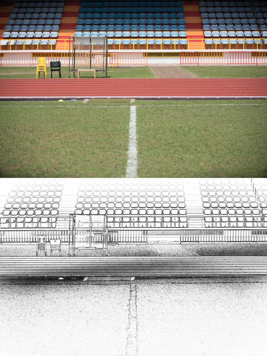
Zoom lenses tend to exhibit more tilt and swing issues than primes on average. This is a Canon EF70-200mm f/2.8 L IS II USM @ 105mm and f/2.8. The centre of the track is 85 feet away. The amount of swing shown here is about 200 microns and can wreck a picture even after stopping down a lot. The B&W illustration is what you get when running Photoshop’s Find Edges filter on the top photo, desaturating and then enhancing the contrast a lot. The darker region indicates where the plane of focus is.
I must stress how difficult it is to appreciate subtle problems, which need to be reliably discerned if you want to be able to determine if your system is holding everything tight to under 10 microns of perfectly straight. 10 microns of focus tilt is by all definitions, very small. Most would not be able to tell even after a hard look. But once you’ve trained yourself to see it, it is visible. It also helps to bear in mind how little 10 microns is. We try to align our cameras to under half that thickness. Typical kitchen-use aluminium foil (not heavy-duty) is about 16 microns thick—feel that between your fingers—Marianne Oelund used that to adjust her lenses, but beware of galvanic corrosion with the metals used for the mount. I think you would be pleased to know the far more elegant solution we found.
10-micron focus shift comparison, 100% magnification. Voigtlander 50mm F2 APO-Lanthar on a7R II @f/2, crop from right-centre image edge. Bottom is shimmed 10 microns more. (Bottom should appear sharper)
How did we arrive at something like 10 microns as our requirement, you might ask? An f/2.8 aperture gives a depth of focus (not field, meaning sensor plane side, not subject plane) of 24 microns for a CoC of 4 microns (close to the a7R II’s pixel pitch), which does not vary by focal length. Any tilt less than what is covered by the depth of focus should not matter. This would be all fine assuming the lens’ field curvature is flat rather than curved, which very few are. So requiring that the entire system is straight to under 10 microns is better assurance. One might also wish to shoot at f/2 instead of f/2.8. In addition, my experience is I can make out a focus tilt of 10 microns with a very sharp lens—depth of field does not mean everything is equally sharp. In practice, I try to adjust my lenses to under 5 microns of perfect relative to the camera.
Update 19 Mar 2021: Tipped off by Joseph telling me he recalls seeing something online about Fujifilm claiming to align their sensors to a 10-micron spec, but not being able to find that later, I Googled and somehow discovered something even better: Fujifilm has published statements that their GFX camera sensors are precisely positioned relative to the bayonet mount to within “a few microns in tolerance”, in consideration of the depth of focus of using a lens at f/2 (that’s only 14 microns worth or less), which is virtually the same our own standards. This is the only camera company I know of that has made public such information about their digital mirrorless cameras (weight tolerance for their mount too!) and to acknowledge the extreme requirements of making superb quality images with wide aperture lenses. How gratifying that we are in agreement.
10-micron focus shift comparison, same as above but at 300% magnification to make the differences more obvious. Voigtlander 50mm F2 APO-Lanthar on a7R II @f/2, crop from right-centre image edge. Bottom is shimmed 10 microns more. (Bottom should appear sharper)
Ignore anyone who tells you wide-angle lenses are affected by this kind of misalignment more than telephotos. It’s a common mistake I too made initially. A 20-micron tilt is a 20-micron tilt. The error doesn’t change because of focal length. Consider this example: a 20-micron extension, say for a 24mm lens intended to focus at a distance of 10,000 metres, now falls at 29 metres. The same error for a 200mm lens intended to focus at 10,000 metres becomes 1650 meters. Oh, you might say, there you go, the wide-angle lens has shifted a lot more! But the apparent depth of field of a 24mm lens is much, much greater, and the magnification of the scene is much less than the telephoto. The combined effect obscures the apparently-greater-distance-shifting-error such that the visual difference is more-or-less the same, assuming all else is equal, as demonstrated by these depth of field calculations below for both lenses at f/2.8, using a CoC of 4 microns; both ranges fall just inside the limit of perceptivity. In actuality, different lens designs and unit-to-unit variations do mess things up in all kinds of ways so a tilt might be more easily observed for a wider angle lens in an arbitrary comparison, but you get the point.
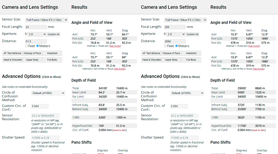
Screenshots from https://www.pointsinfocus.com/tools/depth-of-field-and-equivalent-lens-calculator/
And what kind of tolerances do manufacturers use? We have to consider several sources of information. Cosina has a lens element grinding tolerance of 20 microns and a final polished thickness of 10, measured in 1-micron precision. They claim to cherry-pick elements mated together in a lens to offset the variation error of each. The actual lenses appear to vary more than that for other reasons. This is not the alignment standard for focus tilt but one gets an idea of the kind of tolerances involved. Joseph revealed Phase One’s internal standard for the calibration of the plane of focus of their sensors was supposedly 12 microns, at least as of 2007. That is a pretty tight tolerance, assuming they can achieve it routinely which was not the case, apparently. Canon’s old published tolerance is +/-30 microns or a range of 60 microns for the flange distance on-axis. Smaller sensels and sensors with smaller physical dimensions are more sensitive to positioning errors, as the angular displacement is larger for their size and tinier pixels mean smaller Circles of Confusion – smaller blurs are more easily visible. Roger published two articles for cine cameras and photo cameras recently looking at variation in flange distances which is quite illuminating and seems to confirm Canon’s tolerance standards are achieved in practice, well done Canon!
I’m sure you can now imagine that if the central position can vary so much, the corollary is that alignment for the entire sensor surface to be parallel relative to the bayonet mount is much harder to achieve and probably just isn’t by about as much, if not more, on average. Adding oil to the fire, I discovered more recently that CMOS (and I assume CCD also) sensors themselves aren’t perfectly flat but let’s ignore that for now. They should and perhaps could be, ideally, but the wafers they are based on are apparently not necessarily lapped to be under 1 micron of perfectly flat. The sensor glass filter stack isn’t perfectly flat either and neither is it mounted or taped on (yes, apparently some are stuck on with double-sided tape) perfectly parallel to the imaging sensor.
So, remember the plane of focus of each of our lenses is almost certainly tilted. You can’t use them to evaluate your camera unless you have many lenses, then averaging their errors will and should give you the camera’s error. I’ll tell you how to deal with it later, after we have dealt with the camera.
Your camera’s sensor is (probably) crooked
So let’s say you suspect your camera might be crooked. What can you do about it? The obvious thing might be to send it in for servicing, either to the original manufacturer’s own service centre, one of their appointed repair shops or a trustworthy third-party specialist. Joseph sent his a7R II to one of two authorised repair shops for Sony cameras in the USA, after a long phone conversation. They claimed to have the right kind of machine which can perform an IBIS calibration and adjustment. Believing that the sensor positioning could be rectified by adjusting the IBIS system (IBIS can be controlled on a sub-micron level apparently, for accurate pixel shifting like with some of the newer Sony cameras), off went the camera.
I had my doubts about the success of such an adjustment and we began to scour the web to try and find out how these cameras are put together. There are many teardowns on Youtube, even factory tours where you can see how cameras are assembled, and we were able to glean a lot of useful information from teardown articles by Lensrentals, Kolari Vision and iFixit. The latter shows some very revealing X-ray images of the a7R II IBIS mechanism. The sensor bracket rolls around on small white bearing balls. 5-axis IBIS stabilisation does not mean that the sensor can move fore and aft, unlike what it may seem to sound like. Uh oh. The repair centre IBIS adjustment was not going to work and sure enough, it didn’t.
That meant we got to see just how complex the camera assembly is. To reach the mounting points of the sensor bracket, you would have to take apart almost the entire camera, with multiple screws and flex cable “booby traps” in the way. It is not a job for the faint of heart and makes you uncomfortable after surgery as invasive as this. It feels like you can never truly trust the camera afterwards. It became clear pretty quickly that no service centre could make the kind of adjustment we required. We were on our own.
We also saw from the Lensrentals teardowns that Sony uses shims to adjust the sensor’s position, which for the a7 II was wrongly described as 35, 40 and 45 microns, misled by the abbreviated labels stamped onto the shims. Joseph figured that couldn’t be the case by the relative thickness of them in the pictures, and realised they meant 350, 400 and 450 microns (this error has been avoided in the more recent teardown articles after Roger was informed about it). We have since been able to confirm that the Sony sensor positioning shims indeed come in 50-micron intervals. That was the first clue. We were also able to measure from teardown images that the shim positions are a little over twice the width and height of the sensor itself, so the intervals were more like 25 microns at the sensor’s edge, implying the largest error that cannot be corrected by the shims is half that, ~12.5 microns. This should be OK, except we were pretty sure ours were more crooked than that. Add to that two more a7R IIs borrowed from friends that Joseph looked at. 4 out of 4 were bad.
At that time, we were feeling Sony could do much better by using shims of 25-micron intervals to further halve the maximum error. You’ll soon see why I no longer plan on lobbying them to give us straighter cameras. Nor was there the likelihood they will pay attention to us given how almost nobody seems to complain about the same problem, let alone have a good way of proving it. It was just wishful thinking.
We had an early bad assumption that sensors in cameras like many from Canon and Nikon, mounted with spring-tensioned screws, are virtually always perfectly parallel to their bayonets because this allows for infinitely variable adjustment. If you know the thread pitch of the sensor mounting screws, you can compute how much rotation of the screwdriver in degrees translates into how much vertical displacement. A thread pitch of about 333 microns (the bayonet mount screws are about there) means just under a micron per degree of screw rotation. The sensor mounting screws likely use a smaller thread pitch for finer control. So it is possible to make very fine adjustments to the screws, finer than the intervals that shims come in.
We believed that the more modern CMOS sensor cameras that support live view made using this design, would be aligned by mounting to a reference lens pointing at a resolution chart and the sensor adjusted by looking at the live view feed while turning the spring-tensioned screws. Or better yet, with laser interferometry. Joseph did an evaluation of his Canon EOS 5D Mark II early on which seemed to have well under 10 microns of tilt, reinforcing this false assumption. Later, when I refined our technique for evaluating camera crookedness, it became clear that my own 5D Mark II is some 18-26 microns off, and his should also be more crooked after factoring in the correct error introduced by the measurement method.
So don’t assume spring-tensioned sensors are always perfectly aligned, even if they can be in theory.
We have already learned that Sony Alpha mirrorless cameras (and also some models from Canon, Nikon, Fuji GFX etc.) that use shims for sensor positioning have a positioning error that is limited by the interval thickness of the shims and their installation position relative to the height and width of the sensor’s dimensions. Adjustment by live view is (probably) not done since the entire camera would have to be disassembled to reach the shims each time and replace them. More recently, I was able to spy in a Sony factory tour video at the sensor assembly station, very briefly from 3:59, a special depth gauge jig which appears to use contact measurement off some part of the back of the camera to determine the sensor adjustment. Second clue: Unless the manufacturing precision is so great that all of the components are made perfectly to the desired sizes, and assembled with no skew introduced, which they are certainly not, the backplate of the sensor bracket or the mounting flanges are not parallel to the front side imaging surface. My current hypothesis is that this is the reason why these cameras can never be guaranteed to have sensors within 12.5 microns of perfectly parallel of the bayonet. I wish we knew more about the assembly methods currently used.
At this point, driven by desperation, I suggested to Joseph that we could shim the bayonet mounts ourselves, rather than try to adjust the sensor’s position. It would achieve the same effect. I went off searching for shims in the shape of the mount, while Joseph, more wisely, went straight for small ring shims made by McMaster-Carr. Those shims turned out to vary somewhat from their specified thickness, and many have burrs from being punched from a sheet. It sounds like a problem but Joseph realised later this could be used to our advantage to get intermediate thicknesses not otherwise available. Get a bunch of these for something varying across 1-mil (nominally 25.4 microns). If you add a “base” 20 microns to all other screws, you can have variations of +2/3/4/5/6/7/8 microns. Always have a habit of double-checking every shim’s actual thickness using a micrometre screw gauge of 1-micron resolution.
I switched gears and went looking for similar shims, and so discovered the ones made by Misumi in Japan. They are beautifully made with no burrs (laser cut), quite cheap, available singly and vary very little from the specified thickness. They come in 10, 20, 30, 50, 100 and 200 etc. micron increments with 2, 3, 4, 5, 6mm etc. inner diameter and 3, 4, 5, 6, 7mm etc. outer diameter to cover every possibility. Here is the page for the full list. Misumi is present in 16 countries, hopefully, you can make use of them too. Local shipping has been free so far for me and fast, making this company a godsend. McMaster-Carr will not ship outside the USA, in case you were wondering. You search for the Misumi shims by part number using their system, which I will explain.
This is the string: CIMRSx-x-0.xx
- ‘CIMRS’ refers to ring shims of 304H stainless steel material in individual quantity
- The first ‘x’ refers to the inner diameter in mm, e.g. 2mm which is the only size we have needed thus far
- The second ‘x’ is the outer diameter in mm. I used 3mm for my a7R II and mostly 4mm for lenses
- ‘0.xx’ refers to the thickness in mm. We typically want to have a bunch of 0.01, 0.02, 0.03, 0.05 and 0.10 on hand
For example, CIMRS2-4-0.01 will get you a 304H stainless steel ring shim, 2mm ID, 4mm OD, in 10-micron thickness.
Misumi stainless steel ring shims on finger for scale, 2mm ID, 3 and 4mm OD. The 3mm OD shims are fragile and frustratingly difficult to handle. They stick to everything that has a slightest static charge and get bent easily, which you can see in the photo. 4mm OD shims are much easier to work with.
We can’t start shimming just yet. At this point, we are unable to silo the crookedness to just the camera, independent of the lens. It is a troublesome problem to eliminate the error contributed by the lens if you cannot directly measure the camera. Contact measurement with a depth gauge and non-contact using laser methods were considered. You can only measure at the sensor filter stack from the front side, not the actual light-sensitive plane of the sensor. The cover glass stack is not necessarily parallel to the sensor nor perfectly flat itself, which I was able to confirm to be true later. We also learned from Ilija at Kolari Vision that some are actually taped on so there is little hope of parallelism. You could remove the filter stack (like for a full spectrum conversion), but good luck putting the tip of a depth gauge on the CMOS surface itself without damaging it. Laser interferometry works of course, but the equipment cost is well into the six-figure range and is extremely sensitive to vibrations and alignment and requires arcane expertise to set up and operate. Way beyond the average photographer.
How to adjust your camera’s sensor to be parallel relative to its bayonet mount
Now I shall introduce the brilliant solution discovered by Joseph. We just so happen to own Mirex Tilt-Shift adapters for our landscape work, and this adapter has the unique function of allowing the rear portion of the adapter to freely rotate 360 degrees (primarily to allow the Tilt-Shift function to work at other angles than merely orthogonal to the camera). The Mirex has another wonderful advantage over many other Tilt-Shift adapters – a tripod foot – allowing us to clamp it to the tripod on the lens side, rather than by the camera, so the camera can freely rotate without affecting the optical perspective. This is the trick: We flip the camera 180 degrees relative to the lens. Thus we are able to see what is happening at each edge of the sensor while looking through the same part of the lens, thus eliminating the error contributed by the lens! If the focus plane shifts when the camera is inverted, you will know the sensor is not parallel to the bayonet. Ours is the Pentax 645 to Canon EOS mount Mirex adapter and we are using old manual focus Pentax 645 A lenses, many of which can be found in excellent condition and selling for under 200 USD on eBay from Japanese sellers.
Update 18 Aug 2020: I’ve just learned that Markus is no longer in business making his marvellous Mirex adapters, however, the website is still online at this time. What a tremendous loss to the photographic industry. There are similar Tilt-Shift adapters made by Fotodiox and Kipon that might work too which may require a slightly different setup. I’m not as familiar with them and thus unable to provide more useful comments. You might be able to find used Mirex adapters online. Good luck!
Update 8 Oct 2020: I purchased a Fotodiox Pro Shift EF to E-Mount adapter in the hope to add rise and fall movements in addition to shift for my Mirex setup, and with the intention to explore another means for the camera-flipping-method. A lens like a 70-200, with a tripod collar, could be used with such an adapter that has no foot. Otherwise, you have to pan the camera over after flipping the lens relative to the camera (instead of vice versa) to reposition the subject on the opposite side of the frame to achieve effectively the same thing. For twice the cost you can have the Kipon Shift EF to E-mount adapter which comes with a built-in tripod foot. Kipon’s website is a disaster and is not updated for many new products which they make and this eBay seller used to list this adapter for half as much. Fotodiox has much better documentation on theirs. I have no experience with this Kipon adapter but I know people who both have troubles with Kipon and Fotodiox adapters—light leaks, fit issues, finishing troubles and even adapters getting stuck on lenses. My Fotodiox was quite the disaster when I received it. The inner throat of the adapter is painted matte black to minimise internal reflections but this paint sheds as a fine, flaky powder. You do not want this going inside your camera! I strongly suggest you check any Fotodiox or Kipon adapter you buy before you mount them to your precious and expensive equipment. I had to spend many hours stripping paint, re-greasing and custom flocking my Fotodiox adapter. There were finishing issues too, scratches and dents around the adapter including the important bayonet flanges. These issues were reported to their customer service and escalated to the company owner but unfortunately, there was no follow-up response. I cannot wholeheartedly recommend Fotodiox adapters at this time.
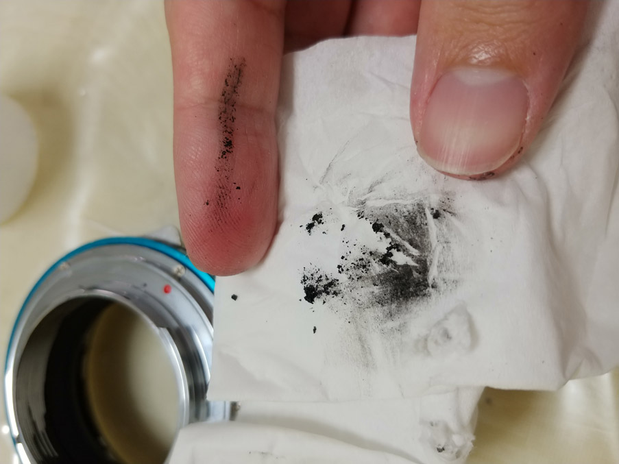
Shedding matte black paint from inner throat of Fotodiox adaper. Beware!
This is the method in detail.
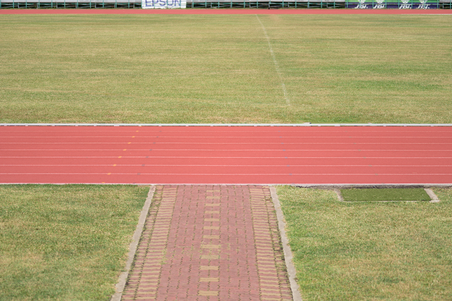
1. You need a giant ruler test scene. (Update 23 July 2021: I’ve come to find this subject matter might be better for determining the plane of focus) The right kind of test subject will save you a great deal of trouble. Ideally, you would want a giant grid laying at your feet stretching out to infinity, large enough from side to side to fill the frame entirely, where the distance of each line is known, regularly spaced with user-adjustable spacing to suit the focussing distance chosen. A large tiled floor comes close if you have access to one that isn’t being crossed constantly by people. My main test subject had been a running track at a stadium near me and I’m set up several steps high on the grandstand. You need to measure the distance accurately from your camera to the focus point. Running track lines are spaced 4 feet apart. I try to focus on the 5th line from the front. If you’re lucky to have a laser rangefinder, great. Measuring tape works fine too, but don’t forget to account for the diagonal distance from the focus point to the camera if you are shooting from an elevated position, not merely the flat ground distance. Given my lines are 4 feet apart, working at a focus distance of about 100 feet is just barely OK with a 150mm lens. If you are focusing at a closer distance with the same focal length, it is better to have distinct detail that can be easily discerned every foot or so.
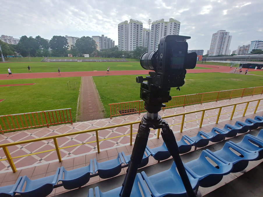
Mirex-Camera-Flipping-Method setup at running track
2. Choose the right focal length. Recall the misconception that wide-angle lenses reveal alignment issues better? They don’t. They often look smeary wide open at the image edges too, making the evaluation of focus too difficult. A medium telephoto tends to be much sharper wide open with minimal aberrations, especially so with these older medium format manual lenses that exhibit poor contrast wide open. The lens aperture is wide open for minimum depth of field in this test to make the focus plane easiest to identify later in step #3. My favourite lens for this is the SMC Pentax-A 645 150mm F3.5 and the SMC Pentax-A 645 120mm F4 Macro. The 200mm is OK too. Joseph has used the SMC Pentax-A 645 75mm F2.8 and I’ve tried the SMC Pentax-A 645 35mm F3.5 but they are rather too messy wide open.
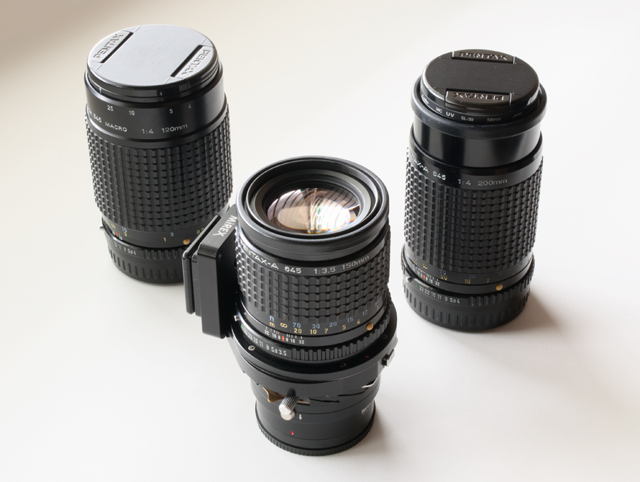
From left to right: SMC Pentax-A 645 120mm F4 Macro, SMC Pentax-A 645 150mm F3.5 on Mirex P645-EF adapter and Novoflex EF-E-mount adapter & SMC Pentax-A 645 200mm F4. Reasonably sharp wide open considering they are older than I am.
3. Do the flip. First, take a picture with the camera horizontal. Then flip it 180 degrees and take another. Make sure not to accidentally induce tilt movement of the adapter during the camera flip, or change the lens focus through all the inversions, or kick the tripod. Needless to say, use sturdy support, mirror-lockup, EFCS, a remote release etc. This is for evaluating focus shift in the swing direction. Put the camera in the vertical orientation, take another. Then flip it 180 degrees again and take one more. This is for evaluating focus shift in the tilt direction. You will have four photos in two pairs, one pair is horizontal for swing and one vertical for tilt.
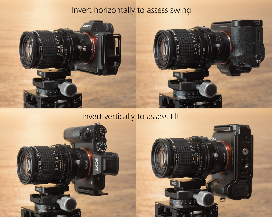
Shown are Sony a7R II, Novoflex EF to E-mount adapter, Mirex Pentax 645 to EF adapter, SMC Pentax-A 645 150mm F3.5 and the four camera positions for the focus shifting test. Do not change focus between inverted pairs.
4. Look at the focus plane and determine where it is. Here comes the most difficult part. First, invert the two flipped images in your image editing software of choice so they are now the right way up. Rename the files so you don’t mix up the camera-inverted ones. Pick an edge of the image to look at. I like to always look at the left image edge regardless of horizontal or vertical orientation. Zoom in to 100% or 200% or 300% or more as needed. Now determine exactly where the centre of the plane of focus is. This is not going to be easy. You have to determine it as precisely as possible. It’s difficult enough to determine which line is most in focus, let alone when it falls between the lines. I like to repeat the observations several days later with fresh eyes, note them down separately and then compare them to my previous observations to be really sure. This step is the greatest source of error using this method. If you cannot trust your vision’s sensitivity, you cannot proceed with confidence. Even among ourselves, we often second guess our observations and need multiple attempts to be assured of determining the plane of focus distance.
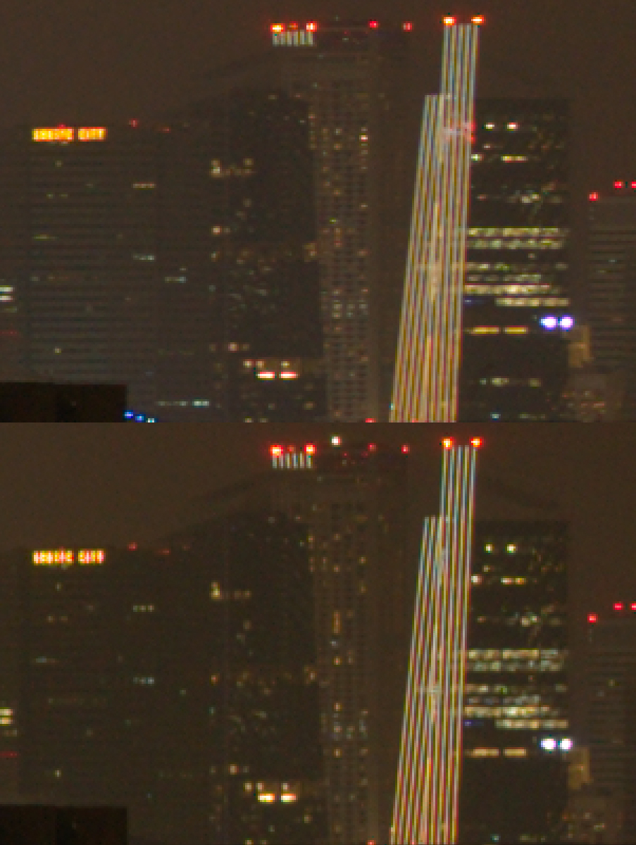
This is what the full-frame image using the running track as a test subject for the Mirex-Camera-Flipping-Method looks like. Shot on an a7R IV and SMC Pentax-A 645 120mm F4 Macro
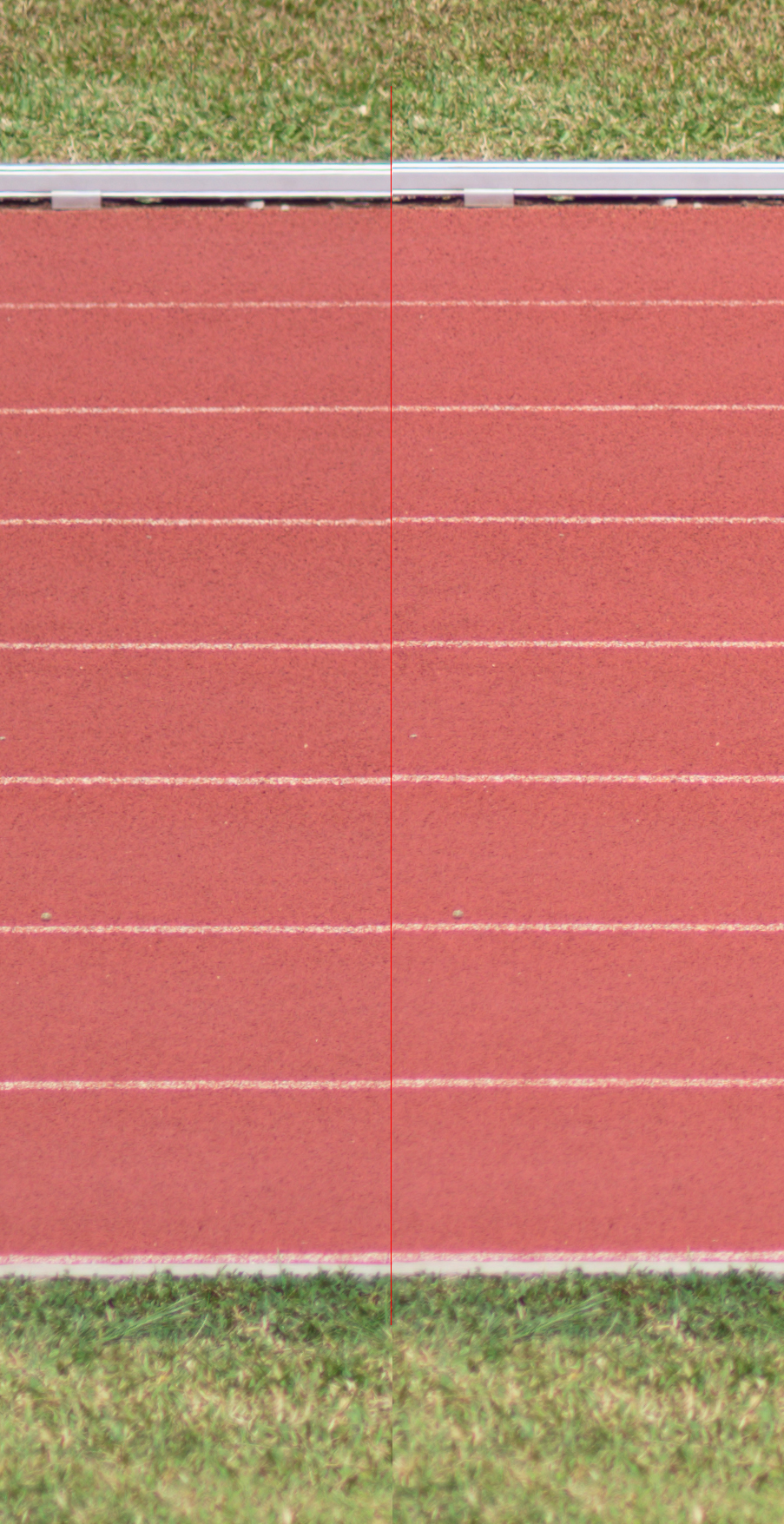
This is a 100% crop from the left edge of the above image, using an SMC Pentax-A 645 120mm F4 Macro on a new out-of-the-box a7R IV. The left side crop is from the camera in the upright position (EVF up), and the right is is from the inverted position, I put in a red line to visually separate them. This represents about 30 microns of swing. Focus is closer in the left crop. This should be relatively easy to spot, despite the old lens being relatively soft wide-open. Looking at 200-300% magnification makes critical evaluation easier of course.
Here is a tougher one, when the camera is only slightly off. I had already shimmed it and was iteratively improving the alignment. These are 100% crops of the left image edge from my a7R II and SMC Pentax-A 645 150mm F3.5, left crop is camera upright (EVF up) and right crop is camera inverted. The red line separates the crops. This difference represents 15-18 microns of shift, about 2-2.5 feet of focus shift. The distance between two white lines is ~4 feet. Can you see it? Rather than looking at the lines only, you can use the degree of blur in the out-of-focus areas to assist your judgment. Look at the grasses and you’ll see one side (right crop) is slightly more blurry than the other.
5. Don’t mix up your orientation. The image formed by a lens on the sensor is inverted and the camera/raw processing software automatically inverts it. When you are looking at the left image edge, that’s actually from the right sensor edge—the camera’s orientation is the rear LCD facing you. When you flip the camera over to look at the bayonet (for your DIY adjustment), the right sensor edge is now on your left. Similarly, the top image edge is actually the bottom sensor edge. Also, if the plane of focus shifts nearer when the camera is inverted, the lens extension is greater, i.e. the inverted sensor edge is now further away from the lens and vice versa. So, left is right, up is down and nearer is further. Or right is left, down is up and further is nearer. Pretty confusing!
6. Use this simple lens formula to compute the lens extension.Lens Extension = Focal Length squared, divided by (Focus Distance minus Focal Length)
Here’s a handy spreadsheet so you can plug in the two focus distances for a flipped-camera pair (in metres or feet) as you determined in step #4 and the focal length of the lens you used, which will give you two lens extension amounts. The difference between the two extension values is the error you want to shim away, after you’ve done the necessary orientation inversions as per step #5 to determine where to put the shims and deducting the remaining error as per step #7 below. If you are looking for the focus plane at some distance in from the image edge (let’s say 3mm inwards at sensor scale) rather than at the edge, you need to adjust the derived lens extension for the actual sensor edge by computing the ratio of the lengths (for a 36mm wide sensor, it would be lens extension divided by 30 then multiplied by 36). So hang on, this is not yet the true sensor swing and/or tilt amount.
7. Eliminate all other errors. We only have one left to account for, which is the wobble of the rotating part of the Mirex adapter which is used to flip the camera. In addition to the Mirex, I also used a Novoflex EF mount to E-mount adapter to get it to mate to my Sony camera. We need to measure the combined thickness of the Novoflex plus the rotating part of the Mirex. I’ve found that cheapo Chinese micrometres on eBay, typically costing less than 40 USD plus shipping each, to be remarkably accurate and repeatable. I have a set of 0-25mm, 25-50mm and 50-75mm micrometres with 1-micron resolution for the measurements I need to make. Make sure to orientate yourself properly. I always use the centre of the left image edge for my evaluation, so I’m measuring at the 3 o’clock position on the adapters. The Mirex’s rear end has to be shifted 5mm offset for the tips of the micrometre to be able to make contact on both sides of the adapter’s bayonet flat surfaces (look at the photo below), but we do not have to account for the parallelism error introduced by the adapter’s shifting mechanism because we do not change that position during this measurement; we are measuring the relative difference only. Then rotate 180 degrees, measure again. The difference is the amount of wobble in the swing direction. Now do it once more for the corresponding vertical position and the flipped position. The difference is the amount of wobble in the tilt direction. Adjust the wobble error for the sensor’s dimensions by dividing by the distance between the measurement points on the diameter of the adapter and then multiply by your sensor dimensions. Deduct this error from the extension difference amount you got in step #6.
This is the amount your sensor is swung and tilted by.
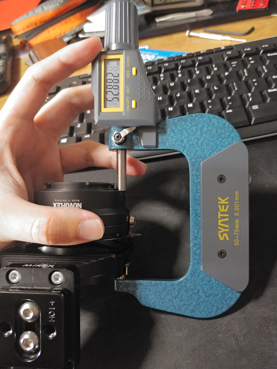
Micrometer measurement of combined Mirex and Novoflex adapter rotation wobble
Neither of us managed to nail the adjustment on the first try, needing multiple operations and more shooting and looking to be absolutely sure. If you find yourself caught in iterative adjustments, know that it’s normal.
Initially, we tried using depth gauges to measure the adapter wobble. You need a stable stand to hold the gauge and a solid base to put the adapters+lens on. It was still too tricky a process. The lens itself would compress and squirm under the pressure of my hand as I tried to rotate the Mirex and it was too difficult to keep the depth gauge tip on the correct position. Too often it would slip into a grove or away from the rim edge of the Novoflex adapter. The micrometre measurement is so much easier, more precise and repeatable. You also don’t have the issue of the depth gauge tip measuring into milling grooves in the adapter’s bayonet rather than at the surface ‘peaks’ which are making contact with the camera’s bayonet. It is absolutely critical to have a good measurement. I could never be confident of my earlier shimming adjustments specifically because of this problem.
Hopefully, your camera’s bayonet has 4 screws instead of 6 like in the newer Sony cameras. The screw positions can be quite awkward like in the Canon EOS R series of cameras (they have 5). The calculations will be less straightforward. You need to measure the distance between the centre of the screws and relate that to the sensor dimensions. The Sony a7R II has four positioned in the corners of an imaginary square shape, parallel to the sensor orientation. Nikon Z cameras are nice that way too, as are the Canon DSLRs, Fuji GFX mirrorless cameras etc. To save you the trouble of measuring, the bayonet screws on the a7R II are 37.5mm apart horizontally and vertically. So the extension amount for the a7R II has to be divided by 24mm or 36mm then multiplied by 37.5mm to derive the shim amount for the top/bottom or left/right screws respectively, the camera orientation is EVF pointing up.
Adding shims will increase the flange distance, obviously. It’s entirely possible that doing this will cause the flange distance on-axis to increase too much for lenses you have that have an infinity focus stop. Such lenses usually have shims just under their bayonet to adjust the infinity focus position, and you may get lucky that one will be of the right thickness which you can remove. I’ve seen such a thing in my Voigtlander 50mm and 65mm lenses, and Joseph has removed a shim in his Voigtlander 21mm F1.4 Nokton lens for just this reason. I believe Zeiss Loxia lenses can be adjusted the same way. It goes without saying that such modifications come with certain risk and will void the manufacturer warranty. Although when done properly, there is no telling that any self-adjustment was made at all and the camera is not damaged in any way. Should you need to send your equipment for professional repair one day, you might have to remove the shims to avoid the possibility that a technician will open up your camera/lens and unexpectedly knock them deep inside the body cavity, potentially ruining something sensitive, perhaps without even realising it.
Infinity-focus adjustment C-shims from just under the bayonet mount in the Voigtlander 50mm F2 APO-Lanthar lens, from left to right are 70, 60, 200 and 200 microns in thickness. These shims are made of brass.
Here are some pictures showing the operation done to my Sony a7R II. I used shims of 2mm inner diameter (ID) and 3mm outer diameter (OD) to avoid pinching against the bayonet spring ring. The space is quite tight. It may be less tight for a different camera design. Joseph was able to successfully use 4mm OD shims. The overlapping edge must sit on top of the spring ring, not under. 2mm ID has been good for every size of screw I’ve encountered so far on the camera or lens.
Shimming Sony a7R II. Notice the tiny 3mm shims resting perfectly around the screw hole, avoiding the bayonet spring ring? The paper rolls hold the shims in place securely. Note also the paper shield to protect the sensor. My a7R II was finally shimmed for the equivalent amount of 19 microns of both swing and tilt at the sensor’s edge.
Did I mention how tiny and fiddly these ring shims are? You need tweezers to grab them. Don’t touch them with your oily fingers directly. I also figured on using a small rectangle of regular office laser paper, rolled up like a joint, to act as a guide and retainer for the ring shim installation. Joseph uses the wire from a paper clip. Thick gauge wire would also work, but be careful not to accidentally scratch a PCB through the screw hole, if there is one below. A diorama modelling plastic rod of the right diameter could work too. I like the paper roll method most, but you need fairly nimble fingers to make them. They are easily bent to thread through the bayonet as you lower it back on top of the newly-placed shims, will not scratch anything in the camera and they unfurl slightly in the screw hole such that they remain in place fairly securely until you’re ready to pull them out. I never just place the shim over the screw hole; it’s too easy to accidentally knock it off and down into infinity and beyond. Bye-bye.
Always ensure adequate support of the bayonet at all screw positions. It’s easy if there are only four screws positioned as if they are four corners of an invisible square, its edges parallel to the image sensor. If the top left screw needs 100 microns of shims, the top right and bottom left need 50 microns. Otherwise, the bayonet will get bent as it’s screwed down onto the mount. Disaster. And the now-bent bayonet flanges will wear out unevenly over time as you mount and un-mount lenses. This is more pernicious than one might expect. The calculations will be more complex when there are more than four screws for the bayonet or they are not equally spaced out. If the screw positions are like the a7R II, and you’ve determined the amount of tilt and swing with the above method, you can simply shim each side of the bayonet in pairs. For swing, you add the same amount of shims to both left or right side screws. For tilt, to both top or bottom screws. If you have corrected for both swing and tilt, there will always be one screw that gets shims from both corrections.
For re-assembly, bayonet mount is threaded through the paper roll posts which are withdrawn one by one as the screws are put back in place. This ensures secure placement of the shims.
I cannot give specific advice for your camera if it isn’t a Sony. Marianne Oelund, whom I mentioned earlier, has been able to do it to a Nikon D800E with aluminium foil. I have heard of others using office paper for a GFX (not so good) or cut pieces out of foil shims. I presume many cameras can be successfully shimmed at the screw holes just under the bayonet mount. Don’t attempt this if you are unsure of yourself. The potential to ruin an otherwise OK camera is always present, though much less likely than total disassembly to reach the sensor itself. When we decided to go ahead to operate on our cameras, they were already over two years old and well past the warrantied period. We were pretty desperate too.
What about IBIS causing potential variation in tilt or flange distance?
We did wonder for a time if IBIS systems introduce enough variation to render our efforts meaningless. Typically an IBIS system consists of the sensor-mounted side rolling around on bearing balls constrained in little wells or cups. Check it out under step #18 of the iFixit teardown. Roger was mistaken in his recent GFX 100 teardown that the tensioning springs holding down the two halves of the sensor IBIS assembly is meant to allow the sensor to move fore and aft or ‘up and down’ as he calls it, to attain the claimed 5-axis IBIS movement. 5-axis IBIS movements correct for pitch, yaw, shift in x-axis, shift in y-axis and roll. So, the first point is that the IBIS system is not designed to tilt or move the sensor forwards or backwards, and IBIS calibration, which can be done by a service centre, aims to centre the sensor in the parked position relative to the mount, not to adjust for tilt.
An important question is, are the bearing balls round enough and are the surfaces they roll on flat enough? I had a short discussion with Brandon Dube in the comments section on the Lensrentals blog when he raised this IBIS issue too. This was what he said:
“The roundness spec on a typical “precision” ball bearing is 1 mil (25 microns). If you assume independent, normally distributed errors then you would expect (25^2 * 3)^0.5 = 43 um of runout from 3 of them. Compound this with the flatness of the Vs, which will be worse. The IBIS systems that use 3 ball bearings place 3 balls in 3 Vs, two of which are in a line. This is not kinematic; the system is not fully constrained.“
This assumption was based on Sony not using ball bearings with a higher roundness spec to reduce cost. 43 microns is over twice the tilt error of my own a7R II’s sensor relative to the bayonet mount, just to put things in perspective. Such variance in tilt would be easily noticeable. I’ve done experiments where I’ve turned off the camera, shook it slightly (the sensor is not parked when turned off) to allow the sensor to ‘roam’ freely and so in the parked position when the camera is turned back on, the sensor is most likely resting on a different point of the ball bearings, which are also likely in a slightly different position on the surface of their retaining ‘wells’. I’ve also turned on IBIS, inflicted some typical hand-held shaking, then turned off IBIS and mounted it back on the tripod. Inducing the self-cleaning function was tried too. There was no visible change to the focus plane with repeats of doing these. I’ve also gone back to the running track months later and repeated the camera-flipping test, and the results were consistent with previous ones for the same shimmed state.
Photographs of bearing balls in these IBIS sensors I’ve seen suggest that the bearings are ceramic or silicon nitride probably, and the best can be made to a roundness specification the deviates no more than 0.01 microns or 100 angstroms. These bearings are relatively expensive though. The cheaper grade types are typically still under a micron of perfectly round and they seem inexpensive after a cursory check online, so cost is not likely a deterrent factor. Silicon Nitride is very hard-wearing and has high thermal stability. The greater contributor to variation error is more likely coming from the flatness of the surfaces than the bearing balls that roll on them.
The third encouraging thing was Roger also mentioned in his flange distance articles that they tested to see if IBIS movement caused changes to the flange distance, but repeated measurements were identical every time. Even though their Denz instrument has a resolution of 10 microns, not 1, and on-axis IBIS-caused tilts would be less than at the sensor’s edge, I think we can assume at this point that it is not something to worry about.
It was also brought to my attention that if you point a Sony Alpha Mirrorless camera with IBIS straight down, say for aerial photography, the sensor does flop forwards a bit. The Sony design doesn’t seem to have the holding springs like the GFX 100 does to prevent flop. I’ve never taken apart a Sony IBIS assembly so I’m not 100% sure, but it’s not visible in any teardown pictures I’ve studied. For what it’s worth, I was not able to notice this flopping in my own tests so far, but I’ll just highlight it in case. It may well be that some units will be more floppy than others.
Adjusting your lenses
So with your camera straightened, you can go back to the business of testing fine quality lenses. Many astute and discerning photographers have taken to purchasing multiple copies of the same lens and doing their own testing to cherry-pick the best one for their use. If the copy is optically decentred, your best bet is to return the lens and look for a better factory-aligned copy. Some opt to have their lens adjusted by a service centre, but after multiple attempts at such a thing and reading anecdotal stories of others who tried the same, I suggest against such hope. Often they would just tell you the lens is ‘within spec’, whatever that means, unless the lens is grossly misaligned. Why would one accept such a lens in the first place, unless it was accidentally dropped and in need of repair? Tilt is a bigger problem and since almost every copy has some slight amount of tilt, one would be returning an unimaginable number of lenses to get lucky that one would fit one’s camera just right. After many lost hopes, I decided a DIY approach was necessary before we drove ourselves mad.
For astrophotography, you need to test your lenses at infinity distance, not 1 metre away. Many lens reviews are done based on shooting test charts very close to the camera, which may give you a false impression for astro work. You may find then that your lenses are crooked, especially after training your eyes to see minuscule differences as mentioned in step #4. They won’t be the same again :-).
If you apply Photoshop’s Find Edges filter and then increase the contrast a lot, you will get a rough idea of the shape of the field curvature and you might even be able to detect instances of decentering. Field curvature often bends nearer off-axis, though a few designs bend away. They are sometimes M or W shaped. They can bend in different directions if you look at the tangential and sagittal plane separately, which is hard to see in real-world testing like this, but you can refer to Lensrentals’ published illustrations. It may be difficult to discern when mixed with all kinds of messes from higher-order aberrations. Straightening a lens that has lots of curvature can be a little complicated.
This is the plane of focus swing test for my new out-of-the-box Voigtlander 50mm F2 APO-Lanthar. It is showing about 90(!) microns of swing. Even the finest lens in the world is not straight! And this was the better of two copies I looked at. The B&W illustration is what you get when running Photoshop’s Find Edges filter on the top photo and enhancing the contrast a lot. The darker region shows where the plane of focus is.
You would likely realise by now that the little ring shims can go under the lens bayonet as they did under the camera’s. Use the same method as you have for the camera to determine the amount of shimming needed. You can get within 5 microns of perfectly parallel relative to the sensor if you are careful. I’ve adjusted all my lenses for astrophotography this way, each with its own set of tricky circumstances.
Canon EF lenses have a rear baffle that needs to be removed (no tools needed, it’s just a clip-on plastic part), then the contacts can be unscrewed and the metal bayonet will come free. If you just pull it up you’ll tear the contacts ribbon cable. Look for disassembly videos if you don’t know what I’m talking about. Many Canon EF lenses (and some Nikons and perhaps others too) have their bayonet mount screws going into a plastic rear barrel. These are usually self-tapping screws and are extraordinarily tight. Be very careful not to slip with the screwdriver and strip them. And when putting them back you won’t be able to feel you are accidentally stripping the threads. It’s pretty awful that way. I’ve found there is usually enough space for 4mm OD shims but space can be very tight in some designs or with a small non-flat base, like in the newer Canon EF70-200mm f/4L IS II USM.
Shimming the Canon EF70-200mm f/4L IS II USM. It received 30+50+100 mics for the top screw, and 30+30+30 for both left and right side screws.
I’ve found the Voigtlander E-mount lenses fairly easy to adjust, so long as you avoid the ribbon cable going to the contacts piece, which does not have to be removed. If you need to shim the bottom right screw, be careful not to overlap the shim on the ribbon cable.
Shimming the Voigtlander 65mm F2 APO-Lanthar Macro. The bayonet need not be detached completely (ribbon cable to the contacts is preventing the bayonet from lifting clear off the lens) to gain access to the shimming points. It received 20+50 mics for the top left screw, 20 mics for the top right screw and 50 mics for the bottom left screw. My Voigtlander 50mm F2 APO-Lanthar (not shown) received 50+30 mics for the top left screw, 20 mics for the top right screw and 30+30 mics for the bottom left screw.
The Sigma 35mm f/1.2 DG DN Art is the easiest lens I’ve ever tried to shim. The bayonet comes free after unscrewing the contacts part and there is ample space for a 5mm OD shim.
Shimming the Sigma 35mm f/1.2 DG DN Art. The little ring shims are sitting on big brass shims used by Sigma to adjust the infinity focus position of the mount. You can use 5mm OD shims for this lens, which gives the nice feeling of being more robust. It received 30+8 mics for the two right side screws. I happened to have two 10-micron Misumi shims that measured a little thinner than specified, which worked in my favour.
A better Giant Ruler (Update 23 July 2021)
A number of people have since written to me to ask for help straightening out their gear. They have been using lawn grass or pavers in car parks as their giant ruler test with a measuring tape in the frame, with peg markers or something of the sort to indicate specific intervals. I then realised that photographing a measuring tape on flat ground can work quite well, since about October last year when Lloyd Chambers reached out for help about his GM 12-24mm lenses.
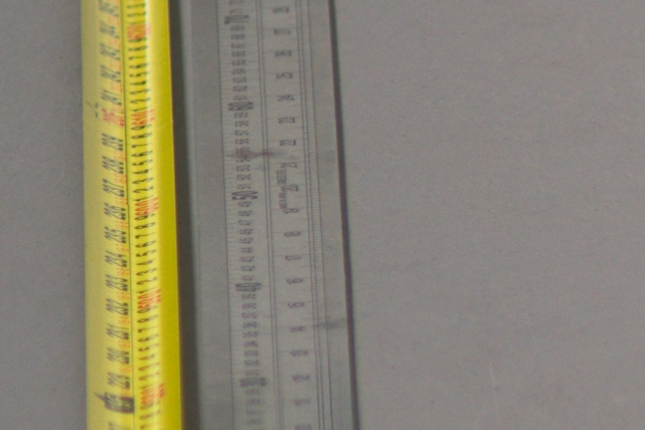
So I wanted to check on my a7R II to see how it’s doing 18 months on and I happen to have a measuring tape that goes to 10 metres. Our common corridor outside the flat has been resurfaced recently and is quite smooth and flat, so I set up right there. I also positioned a stainless steel metre ruler where the focus plane will fall, for additional subject matter to read off from. I used all possible cues together with Photoshop’s Find Edges filter to assist in determining the plane of focus. The camera’s sensor was positioned directly above the zero-point on the tape measure, guided by a weighted piece of twine. The centre of the sensor measured 135cm off the ground and the diagonal distance to the tape measure was calculated and used, rather than merely reading off the ground distance.
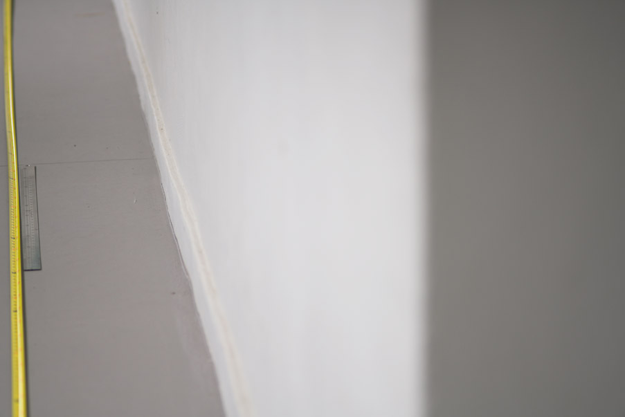
Photographing measuring tape with focus at 6 meters (ground distance) from camera, using a 1-metre stainless steel ruler to assist in finding the plane of focus more precisely. Camera in upright horizontal position and then flipped to discover the swing error. Repeat in the vertical orientation for the tilt error.
Some computations first. For a 150mm lens focused at 9 meters, a 1cm focus shift represents 2.9 microns shift at the sensor. But I find can’t make out the line markings well enough at 9 metres. The system simply doesn’t resolve that level of detail. I was able to see the lines more clearly when focused at 6 metres. A 1cm difference is then 6.6 microns at the sensor. If I can read down to 0.5cm, the error would be under 3.3 microns (just barely possible with the help of the Find Edges filter). Compare this to the running track test subject, painted lines 4 feet apart at 97 feet from the camera, which gives an error of ~32 microns. Guessing the plane of focus to within two feet was much harder and I was never really sure of it. Even so, that is ~16 microns of error, and I would like it well under 10.
100% view of the focussed portion of the rulers. On high ppi displays, a 200% upsampled (nearest neighbour) version is displayed.
You can choose to focus at any distance you want if you’re testing the camera’s crookedness. Flipping the camera relative to the lens eliminates the lens’s error, so there is no need to focus far away. If you are focusing relatively nearby, you need detail at smaller intervals for your reading error to be as low as possible.
I also re-measured my Mirex+Novoflex combined wobble. The cheapo Chinese micrometre gave near-identical readings in all four flipping orientations. It was either exactly the same readouts as 1.5 years ago, or 1-2 microns less. Less makes sense, as the adapter should get thinner as it wears down from use. My Mirex gets thicker when flipped in the swing direction by 1.25 microns worth when adjusted to the a7R II’s sensor’s dimensions. It gets thicker by 5.43 microns when flipped for the tilt orientation. Remarkably precise machining by the Germans!
I double-checked everything as best as I could. It appears that my a7R II has 4.45 microns of residual swing and 1.25 microns of tilt based on my guess of where the plane of focus is. I’m not suggesting that I can see 0.05 microns of tilt. It’s just what the calculated amount is for the positions for focus I’ve picked, less the adapers’ error. The reading error should be under 6 microns, maybe under 3. If so, the swing is such that I cannot shim any more precisely given the limited thickness intervals of the Misumi shims. The tilt is essentially perfect. A highly pleasing result!
Update 28 Aug 2024: This method has been further advanced through the use of a custom designed aliasing ruler, as described in a more recent article. The observation precision is significantly improved by it and should not be underestimated.
Yet more alignment pitfalls due to bayonet machining precision or lack thereof
Recently, I acquired a Sony a7R IV and naturally, I tested it to see if the sensor is straight. It was tilted by some 10-15 microns and swung by about 30. That makes 5 out of 5 bad Sonys, if you are still counting. I also noticed that my native mount lenses were not mating to it the same way as they were to my a7R II. As it turns out, the bayonets are not machined precisely enough to mate identically across different cameras with different lenses! My Sigma 35mm mates the same way, while my Voigtlander 50mm mating difference is causing some 15-20 microns of tilt, and my Voigtlander 65mm shows about 30 microns in tilt of mating difference. If I look between the bayonets using a window or something bright like my computer display as the background, I see that there is a gap between the bayonets on one side which changes. It may or may not change in other spots around the mount. Using feeler gauges, I can measure how much the gap varies and it corresponds quite well to the resultant focus shift I observe on the camera.
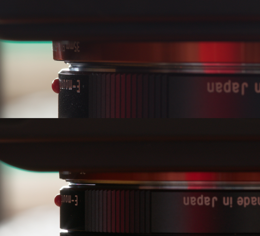
Bayonet gap is not visible between Voigtlander 65mm lens and an a7R II (top) but is visible when mated to an a7R IV (bottom). Not shown are the other sides of the bayonets which mate the same way, thus a tilt is induced. Also not shown is my Sigma 35mm lens which mates identically to these same cameras.
What this means is that lenses you adjust perfectly to your now perfectly aligned camera will not necessarily be straight on another camera, even if that were also perfectly aligned, because of bayonet differences. Consider it a camera-specific adjustment. There’s nothing we can do about this, unfortunately. Maybe you will get lucky and the cameras you buy will have near-identical bayonets. I wouldn’t bet on it. I learned from Brandon Dube that the specially made bayonet mounts used for OLAF have a runout of under 10 microns across 40mm. Roger has said these cost 8000-10,000 USD each and take a long time to make to order. The ones on your lenses and cameras are not going to be machined as precisely. This bayonet precision issue is the reason why I no longer believe that using a reference lens to test your camera can assuredly tell you anything useful. And it is probably one of the reasons for continued variation in sensor alignment of cameras that are mounted on a master lens, using live view looking at a resolution chart to adjust spring-tensioned screws. It would be meaningless to require the sensor positioning tolerance to exceed the bayonet machining tolerance: any gains would immediately be negated.
Possibly another good method for measuring camera crookedness
I’ve been wanting a more precise and different method of making such a measurement rather than relying solely on Joseph’s Mirex-Camera-Flipping-Method and be at the mercy of visual judgement to see where the plane of focus is in a landscape with a giant ruler.
We considered several ideas, one of which was using laser measurements (laser micrometers was what we looked at initially) and Brandon Dube has suggested laser interferometry on the Lensrentals blog. I had some discussion with Ilija at Kolari Vision and he raised the issue of reflectance of the various surfaces in front of the sensor—5 in total for Sony Alpha mirrorless. What surface are you measuring? And the IR filter is highly reflective to visible light but the bayer CFA is not, while the bayer CFA is quite IR reflective. It makes choosing the ideal wavelength for the laser seem troublesome, or perhaps not.
Earlier this year, I learned about Keyance’s confocal white light displacement sensors and their advantages vs lasers and a sales representative arranged a demonstration for me. I learned these are some of the major differences between confocal vs laser displacement sensors that are advantageous for our situation:
1. They are much less sensitive to surface curvature/perpendicularity of the sensor to the measurement surface and aren’t bothered by reflective or mirror surfaces. Laser sensors need the measurement surface to be within 1 or 2 degrees parallel to the sensor. Mirrored surfaces and glass are especially hard for lasers needing strict alignment requirements while confocal is much more forgiving.
2. Confocal can do multi-layer thickness measurements for transparent materials concurrently, up to 6 surfaces for Keyence’s sensors (e.g. three planes of glass). We were able to detect 4 surfaces (missing one) on the Sony sensor with the Keyence 070 sensor. The 030 sensor was able to detect 5 surfaces. The 070 sensor is the less precise model but can measure greater depth differences at once. It appears to be that the CMOS surface is reflective enough to be measured with visible light.
3. The measuring rate is user adjustable. We used 256 but mostly 1000 Hz for very stable and repeatable measurements. The setup was quite insensitive to vibrations this way. Lasers are very sensitive to vibrations.
4. It can measure various material surfaces with varying surface roughness with ease and with great measurement stability, repeatability and is immune to reflection interference. Scatter from specular surfaces can interfere with laser displacement sensors and varying surface roughness can cause the readouts to jump a lot making it difficult to judge what the true measurement is, while confocal readouts are very steady.
5. White light confocal sensors also do not generate any meaningful amount of heat at the measurement head, so the measurements are stable over time compared to laser displacement sensors which tend to heat up, resulting in thermal distortion of the mounting jig.
During the demonstration, I learned two more things. My Sony CMOS sensor at the bayer CFA surface appears to be warped. I say ‘appears’ because we did not have enough time to make sufficient measurements to properly verify this. I was told by the Keyence representative that the silicon wafers and CMOS sensors he has measured are all warped. He thinks that the warping usually doesn’t exceed 10 microns for camera sensors, but he didn’t have actual data on that. He showed me a measurement from an actual 300mm diameter wafer pulled from a production line, and the warping was ~170 microns between the highest and lowest points across the wafer, in a gentle sine wave shape. Camera sensors are a lot less wide across, so if we assume Sony makes their wafers to half as warped for the same diameter, and since these 35mm format sensors are roughly one-tenth of the diameter of this wafer, then we could expect our sensors to have about 10 microns of warping. It may likely be well under that on average, probably not anything to worry about. The measurements also revealed that the sensor cover glass was not perfectly parallel to the light-sensitive plane of the sensor. You can forget about making accurate contact measurements off the front side of the sensor.
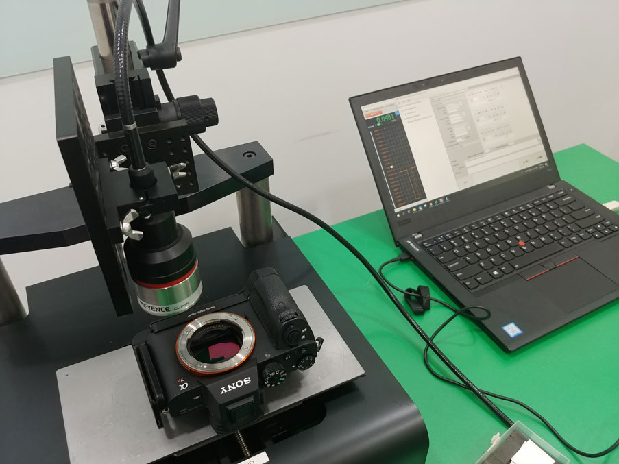
Taking measurements off the a7R II using Keyence 070 confocal white light displacement sensor
The cost of these sensors are pretty substantial compared to the Mirex adapter, though they are only about 5% of the cost of a $225,000 ZYGO Verifire MST laser interferometer. The measurement range is a significant limitation—the 070 sensor has a measurement range of 20mm, so anything thicker than the Sony Alpha mirrorless camera’s flange distance could not be measured unless combined with a high-precision X-Y-Z table, with the major contributor of z-axis error likely from the table unit. Such a table will easily exceed the cost of the confocal white light sensor. It’s not something the average photographer would bother with.
Conclusion
After all this time, the Mirex-Camera-Flipping-Method (how’s MCFM for an abbreviation?) still stands as the least costly, most elegant way to discern errors between the camera and the lens. Its primary limitation is one’s visual power. More precise determination can only be had with significantly more costly tools, at least 50x more expensive, but if you are a careful worker, MCFM works well enough. You don’t need to go overboard and try to get everything to be straight to under 1 micron, stars are actually a little more forgiving than that, especially if they are low in contrast. You should be able to get away with a 10-micron tilt, but 20, probably not if your eyes are good and you’re being fussy.
If you’ve managed to come this far with me, congratulations. We ourselves have been on this wild ride chasing down microns for over 40 months, and it hasn’t seemed to end. The length of this discourse reflects the multitude of complex issues that had to be dealt with. But now you won’t have to spend nearly as much time as we did figuring out how to straighten out your gear. And we can finally get back to the business of making great pictures again.
Joseph Holmes has also written extensively about our findings but has yet to publish. I will provide a link to his article when he does.
Samuel Chia
First published 14 August 2020
Latest revision 23 July 2021. Significant changes have been made to include more useful information discovered since the time of publishing this article.
Recommended further reading:
https://www.dpreview.com/opinion/4042117089/roger-cicala-why-i-dont-use-an-mtf-bench-to-test-my-own-lenses
https://www.dpreview.com/articles/1351719699/roger-cicala-field-curvature-for-fun-and-profit
2 Comments
Comments are Disabled
[…] It’s not often I find myself outgeeked, but I have. This article is an incredibly good (it’s long, but worth it) read on sensor tilt. I recommend […]
[…] as my own independent dealings with other photographers and printmakers, I’ve come to realise my senses are more acute than most. So if you tell me your printer is free of such problems and I should go eat my hat, I’ll say: […]